Difference between revisions of "Pro-2066 Discriminator Tap"
From The RadioReference Wiki
(Created page with "Photo 1|thumb Photo 2|thumb <br> ;'''Warning! THIS MODIFICATION WILL VOID ANY WARRANTY! ATTEMPT THIS MODIFICAT...") |
|||
| Line 19: | Line 19: | ||
* Wire cutters | * Wire cutters | ||
<br> | <br> | ||
| − | ;''' | + | ;'''Modification Procedure''' |
| − | |||
| − | |||
| − | |||
#Unplug the AC/DC power supply; remove the power plug connector from the receiver; unplug the antenna connector and remove the bottom receiver cover. | #Unplug the AC/DC power supply; remove the power plug connector from the receiver; unplug the antenna connector and remove the bottom receiver cover. | ||
#Cut excess wire from the 10K resistor leaving two approximately 1/2 inch wire "legs". | #Cut excess wire from the 10K resistor leaving two approximately 1/2 inch wire "legs". | ||
| Line 35: | Line 32: | ||
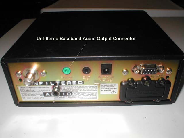
#Reconnect the receiver's speaker wire connector to the pc board and replace the BOTTOM case cover. See [[Media:Jackmount.jpg|Photo 3]] of the rear chassis mounted connector. | #Reconnect the receiver's speaker wire connector to the pc board and replace the BOTTOM case cover. See [[Media:Jackmount.jpg|Photo 3]] of the rear chassis mounted connector. | ||
#Reconnect the power supply and antenna connector to the receiver. Turn on the receiver. If receiver performance is not within specification, check the resistor/cable routing/connections. Inspect to ensure the resistor is not shorting out. If it is provide additional insulation around it. Replace the case cover and reconnect the power supply and antenna. | #Reconnect the power supply and antenna connector to the receiver. Turn on the receiver. If receiver performance is not within specification, check the resistor/cable routing/connections. Inspect to ensure the resistor is not shorting out. If it is provide additional insulation around it. Replace the case cover and reconnect the power supply and antenna. | ||
| − | |||
| − | |||
<br> | <br> | ||
; Parts/Component Sources: | ; Parts/Component Sources: | ||
* 10K Ohm 1/4W Resistor | * 10K Ohm 1/4W Resistor | ||
[http://www.radioshack.com Radio Shack] | [http://www.radioshack.com Radio Shack] | ||
| − | |||
| − | |||
| − | |||
| − | |||
| − | |||
| − | |||
<br> | <br> | ||
; Related Links: | ; Related Links: | ||
* [http://www.radioreference.com Trunked Radio Information] | * [http://www.radioreference.com Trunked Radio Information] | ||
| − | + | Thanks to John Wilson W4UVV for format of article. | |
[[Category:Modifications]] | [[Category:Modifications]] | ||
Revision as of 23:20, 31 July 2011


- Warning! THIS MODIFICATION WILL VOID ANY WARRANTY! ATTEMPT THIS MODIFICATION AT YOUR OWN RISK!
The modification is neither complicated nor expensive but it does require the person to have a steady hand
and good concentration.
- Modification recommended components:
Purchased components cost estimated at approximately $15.00.
- Philips screwdriver
- Shielded insulated audio/visual cable (Approximately 18 inches)
- 5 watt soldering iron
- 60/40 solder
- 1/8" Mono Audio Jack
- 3/8 inch power drill with various size drill bits 7/32 inch to 1/4 inch
- Pliers
- One 10K Ohm 1/4W Resistor
- Electrical tape
- Wire cutters
- Modification Procedure
- Unplug the AC/DC power supply; remove the power plug connector from the receiver; unplug the antenna connector and remove the bottom receiver cover.
- Cut excess wire from the 10K resistor leaving two approximately 1/2 inch wire "legs".
- Remove ribbon cable from AF board by pulling out of PC board connector.
- Unsolder RF connector from AF board
- Remove 4 screws holding AF board down
- Locate MC3661CD AF IC and tap point next to Pin #9.
- Solder wire to tap point
- Add 10K resistor inline with wire.
- Drill hole for 1/8" Audio Jack
- Mount jack and solder wire to terminals. Center conductor is audio frequency. Chassis is ground.
- Reconnect the receiver's speaker wire connector to the pc board and replace the BOTTOM case cover. See Photo 3 of the rear chassis mounted connector.
- Reconnect the power supply and antenna connector to the receiver. Turn on the receiver. If receiver performance is not within specification, check the resistor/cable routing/connections. Inspect to ensure the resistor is not shorting out. If it is provide additional insulation around it. Replace the case cover and reconnect the power supply and antenna.
- Parts/Component Sources
- 10K Ohm 1/4W Resistor
- Related Links
Thanks to John Wilson W4UVV for format of article.