Digital Voice Conversion Method
From The RadioReference Wiki
Contents
Digital Voice Conversion Method
Developed by: Joseph A Cardani
Objective
A method to recover digital voice on public safety APCO-25, ProVoice, and Aegis digital radio systems.
Process
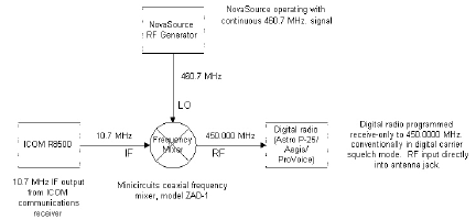
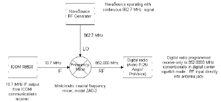
A communication receiver’s 10.7 MHz IF is mixed with a constant signal from an RF generator to produce an RF signal that is directly connected to the antenna input of an APCO P-25 or M/A-COM ProVoice/Aegis capable 2-way radio. This will allow digital voice decoding of any signal that is tuned on the communications receiver.
Benefits
- The method is not band dependent – any channel that can be tuned by the communications receiver can be decoded. Other methods, such as a dedicated 2-way radio, can only operate on 800 MHz, UHF, etc.
- The 2-way digital radio provides excellent specifications and vocoding versus a consumer grade scanner.
- Trunk tracking is not performed by the 2-way radio; it is done by 3rd party software. This bypasses any legal issues with the equipment vendor. In addition, the 2-way radio is programmed conventionally with transmit disabled so there is no risk of accidentally transmitting on the frequency.
Applications
- Monitoring EDACS ESK Systems, including ProVoice ESK systems.
- Monitoring EDACS AEGIS Systems
Components
Communications Receivers:
- ICOM R-7000 or R-7100 or R-8500 or R-9000 (all have 10.7 IF output)
NovaSource M2 RF Generator: http://www.nova-eng.com
- NS2-0800104 for 800 MHz operation
- NS2-0320104 for UHF operation
Minicircuits Coaxial Frequency Mixer: http://www.minicircuits.com
- ZAD-2 for 800 MHz operation (rated to 1 GHz)
- ZAD-1 for UHF operation (rated to 500 MHz)
Diagrams
Calculations
LO freq (Signal Generator Output) = Desired Output Frequency + Receiver IF
So if the desired frequency of the receiving radio is 852.000 MHz and the ICOM's IF is 10.7 MHz, then the LO frequency of the Signal Generator should be 862.700 Mhz (852.000 MHz + 10.7 MHz = 862.700 MHz).
Parts List
1	NovaSource M2 RF Generator @				$699.00
1	Minicircuits ZAD-1 or ZAD-2 Mixer &			$43.95 to $49.95
1	DC Block (Model 8080)*					$49.00
1	SMA/M to BNC/M Cable (Model RFW-5366-12)*		$18.00
1	BNC/F to SMA/F Adapter (Model 5014)*			$22.00
1	RCA/M to BNC/F Adapter (Cat # 278-280 or 278-301)**	$3.99
2	BNC patch cords (BNC/M both ends)
1       Communications Receiver/Scanner with 10.7 IF Output
1       Motorola ASTRO Saber or Spectra (450 MHz - 512 MHz)
1       Motorola ASTRO Saber or Spectra (800 MHz)
@ Available from Nova Engineering http://www.nova-eng.com 1-800-341-NOVA
& Available from Minicircuits http://www.minicircuits.com 1-718-934-4500
* Available from Sun Moon Electronics http://www.sunmn.com 1-800-715-4396
** Available from local Radio Shack
Connections
A sample setup using a Motorola ASTRO Saber.
Step 1 -- Connect the RCA/M to BNC/F adapter to the 10.7 IF output of the ICOM receiver (this is a female RCA jack).
Step 2 -- Connect the DC block to the adapter above.
Step 3 -- Connect one BNC to BNC cable from the DC block to the IF input of the Minicircuits mixer.
Step 4 -- Connect the SMA/M to BNC/M cable from the NovaSource RF Generator (SMA/F jack) to the LO input of the Minicircuits mixer (BNC/F jack).
Step 5 -- Remove the antenna from the Astro Saber and connect the BNC/F to SMA/F adapter to the antenna input (SMA/M jack)
Step 6 -- Connect the other BNC patch cord from the BNC/F to SMA/F adapter that is attached to the Saber to the RF output of the Minicircuits mixer (BNC/F jack).

