Difference between revisions of "10.7 MHz IF Output for the 2500"
From The RadioReference Wiki
| Line 1: | Line 1: | ||
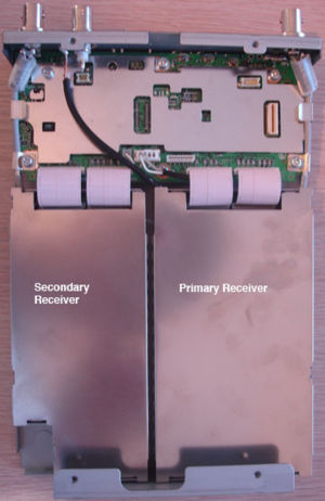
| − | [[Image:PCR2500-1.jpg|thumb|Inside View After Taking Cover Off]] | + | [[Image:PCR2500-1.jpg|thumb|right|Inside View After Taking Cover Off]] |
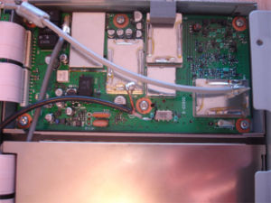
| − | [[Image:PCR2500- | + | [[Image:PCR2500-2.jpg|thumb|right|Lead wire from tap point to coax]] |
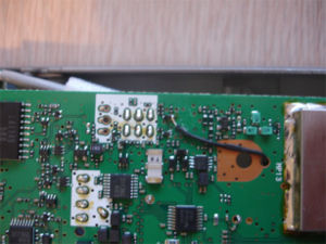
| − | [[Image:PCR2500- | + | [[Image:PCR2500-3.jpg|thumb|right|Tap Point on Receiver #1]] |
| + | |||
| + | ---- | ||
| + | |||
| + | Word of warning - the tap point is extremely small, and not for the faint of heart. I actually went out | ||
| + | and purchased a professional Weller Soldering iron and special soldering tip just for this task. Using | ||
| + | the least amount of heat possible, I glued a pre-tinned small piece of wire next to the tap point, and | ||
| + | then dragged some solder from the VERY small surface mount point to the wire. I then ran this 1 1/2 | ||
| + | inch short length of wire up through the hole next to the center screw, and soldered some shielded | ||
| + | cable to that for the run to the BNC connector. | ||
Revision as of 18:01, 15 November 2006
Word of warning - the tap point is extremely small, and not for the faint of heart. I actually went out
and purchased a professional Weller Soldering iron and special soldering tip just for this task. Using
the least amount of heat possible, I glued a pre-tinned small piece of wire next to the tap point, and
then dragged some solder from the VERY small surface mount point to the wire. I then ran this 1 1/2
inch short length of wire up through the hole next to the center screw, and soldered some shielded
cable to that for the run to the BNC connector.


