Pro-2066 Discriminator Tap
From The RadioReference Wiki
Revision as of 18:07, 31 July 2011 by Mrunyan (talk | contribs) (Created page with "Photo 1|thumb Photo 2|thumb <br> ;'''Warning! THIS MODIFICATION WILL VOID ANY WARRANTY! ATTEMPT THIS MODIFICAT...")


- Warning! THIS MODIFICATION WILL VOID ANY WARRANTY! ATTEMPT THIS MODIFICATION AT YOUR OWN RISK!
The modification is neither complicated nor expensive but it does require the person to have a steady hand
and good concentration.
- Modification recommended components:
Purchased components cost estimated at approximately $15.00.
- Philips screwdriver
- Shielded insulated audio/visual cable (Approximately 18 inches)
- 5 watt soldering iron
- 60/40 solder
- 1/8" Mono Audio Jack
- 3/8 inch power drill with various size drill bits 7/32 inch to 1/4 inch
- Pliers
- One 10K Ohm 1/4W Resistor
- Electrical tape
- Wire cutters
- Let's Do It.
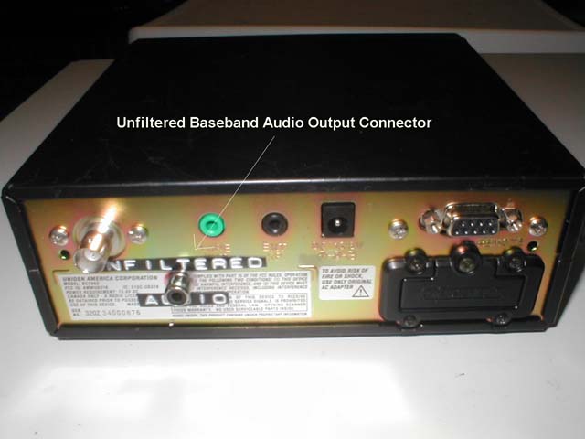
The following modification steps are provided as recommendations and guidance only. There are other ways to do this modification as you may choose, but the below method has proven to work without adversely impacting the scanner's performance. The main objective is to locate the pc board's desired solder/tap point; solder one end of a .01 mF disc ceramic capacitor there, solder the other end to the center conductor of an appropriate cut length of A/V cable; connect the A/V braid to ground; route the other end of the A/V to a rear chassis mounted RCA female connector and solder. The target soldering pc board location is labeled "LND6 FM Det. Out". See Photo 1. Tone decoding attempts at the more obvious pc board location labeled "LND8 CTCSS Det." were unsuccessful.
- Steps
- Unplug the AC/DC power supply; remove the power plug connector from the receiver; unplug the antenna connector and remove the bottom receiver cover.
- Cut excess wire from the 10K resistor leaving two approximately 1/2 inch wire "legs".
- Remove ribbon cable from AF board by pulling out of PC board connector.
- Unsolder RF connector from AF board
- Remove 4 screws holding AF board down
- Locate MC3661CD AF IC and tap point next to Pin #9.
- Solder wire to tap point
- Add 10K resistor inline with wire.
- Drill hole for 1/8" Audio Jack
- Mount jack and solder wire to terminals. Center conductor is audio frequency. Chassis is ground.
- Reconnect the receiver's speaker wire connector to the pc board and replace the BOTTOM case cover. See Photo 3 of the rear chassis mounted connector.
- Reconnect the power supply and antenna connector to the receiver. Turn on the receiver. If receiver performance is not within specification, check the resistor/cable routing/connections. Inspect to ensure the resistor is not shorting out. If it is provide additional insulation around it. Replace the case cover and reconnect the power supply and antenna.
- Calm down and stop shaking. The modification is finished.
- Parts/Component Sources
- 10K Ohm 1/4W Resistor
- Shield Phono Jacks Panel Mount
Radio Shack Catalog Number 272-346
- Audio Visual Insulated Cable
Radio Shack Catalog Number 15-1591
- Related Links