BC796D Discriminator Mod
From The RadioReference Wiki
By John Wilson W4UVV (w4uvv at amsat dot org)
- First things first.
Why modify a scanners audio output when one of its features is detection of analog and digital CTCSS sub-audible tones when scanning analog signals in the conventional or digital modes? The reasons are
this additional user feature affords several monitoring advantages. First, the receiver's CTCSS search cycle is slow.
When a new analog transmission is detected, analog CTCSS tones are checked beginning with the lowest tone and
progressing to the highest. If no match digital tones next are checked in the same sequence. Sometimes the CTCSS
tone is not identified on short duration transmissions as they terminate before the correct CTCSS tone, if present,
is identified. Secondly, with a direct discriminator audio output connection to an external CTCSS tone decoder the
tone, if present, is displayed immediately. Thirdly, this connection to a computer via a Level 2 or Level 4
dataslicer and RS232 computer comm port interface offers a monitoring advantage. It eliminates the need for a
second receiver/scanner tuned to a 400 or 800 mhz. data control channel for executing Trunker 3.8.3, MS DOS software
for Motorola Type I/II and Etrunk 3.8.1 (EDACS) 400/800 mhz. trunked radio systems(TRS).
- Warning! THIS MODIFICATION WILL VOID ANY BC796D WARRANTY! ATTEMPT THIS MODIFICATION AT YOUR OWN RISK!
The modification is neither complicated nor expensive but it does require the person to have a steady hand
and good concentration.
- Modification recommended components:
Purchased components cost estimated at approximately $15.00.
- Philips screwdriver
- Shielded insulated audio/visual cable (Approximately 18 inches)
- 5 watt soldering iron
- 60/40 solder
- One female RCA chassis connector. (I prefer using RCA male/female connectors but comparable male/female RF connectors may be substituted)
- 3/8 inch power drill with various size drill bits 7/32 inch to 1/4 inch
- Pliers
- Boxcutter or trimming knife
- One .01 mF disc ceramic capacitor
- Electrical tape
- Silicone sealant dispenser
- Wire cutters
- Let's Do It.
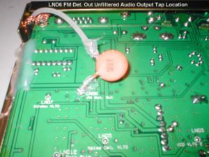
The following modification steps are provided as recommendations and guidance only. There are other ways to do this modification as you may choose, but the below method has proven to work without adversely impacting the scanner's performance. The main objective is to locate the pc board's desired solder/tap point; solder one end of a .01 mF disc ceramic capacitor there, solder the other end to the center conductor of an appropriate cut length of A/V cable; connect the A/V braid to ground; route the other end of the A/V to a rear chassis mounted RCA female connector and solder. The target soldering pc board location is labeled "LND6 FM Det. Out". See Photo 1. Tone decoding attempts at the more obvious pc board location labeled "LND8 CTCSS Det." were unsuccessful.
- Steps
- Unplug the AC/DC power supply; remove the power plug connector from the receiver; unplug the antenna connector and remove the TOP receiver cover.
- Cut the male connector from each end of the insulated shielded A/V cable and remove approximately 1 3/4 inches of outside insulation from one end and separate the shielded ground braid from the insulated center conductor.
- Cut excess wire from the .01 mF disc ceramic capacitor leaving two approximately 1/2 inch wire "legs".
- WARNING! DO NOT USE A SOLDERING IRON RATED HIGHER THAN 5 WATTS. USING A HIGHER WATTAGE IRON MAY DAMAGE PC BOARD TRACES OR OTHER CONNECTIONS AND/OR POSSIBLY DAMAGE MOUNTED COMPONENTS. Heat one end of the capacitor wire "leg" and apply a very small amount of solder. CAREFULLY using only the minimum amount of solder and heat necessary to effect a good soldered connection at the "LND6 FM Det. Out" point. Solder that wire "leg" to it. Remove any solder debris and place a small piece of electrical tape on the pc board beneath where the capacitor will lie close and parallel to it.
- Viewing the receiver front to rear carefully route the other end of the A/V cable through the open area at the rear left corner.
- At this location a Philips screw secures the left rear pc board to the chassis. Loosen it and wrap an appropriate length of shielded ground braid for a friction fit. Ensure enough length of shielded braid and center conductor cable remain to solder it non-stressed to the .01 mF disc ceramic capacitor. Tighten the screw. Remove any excess braided ground shield.
- Remove approximately 1/4 inch insulation from the center conductor A/V cable and wrap around the remaining capacitor wire "leg". Solder the connection. Insure when both lay parallel to the pc board bottom neither touches any trace or connection. Apply a small amount of silicone sealant to each exposed wire "leg" of the .01 mF disc ceramic capacitor. See Photo 1 for what the modification looks like at this point.
- Replace the receiver's TOP case cover; remove the receiver's BOTTOM case cover and disconnect the speaker wire connector from the pc board.
- Viewed from the outside rear to front prepare to drill a small "pilot" hole using a 7/32 inch bit or one of similar small diameter. I chose to drill the RCA connector mount hole approximately 3/4 inch down from the top and approximately 2 inches inward from the outside rear chassis. This locates the RCA female chassis connector in an open area away from an inside rear chassis metal flange and DC power connector.
- CAREFULLY and SLOWLY drill the target pilot hole. Increase the hole size using slightly larger bits until 1/4 inch size maximum.
- Mount the RCA female chassis connector securing it with the threaded nut and tighten using pliers. Ensure the ground solder connector flange is bent slightly outward.
- Cut any excess A/V cable beyond the place after removing approximately 1 3/4 inches of outer insulation that allows non-stressed solder connections to the RCA female chassis connector.
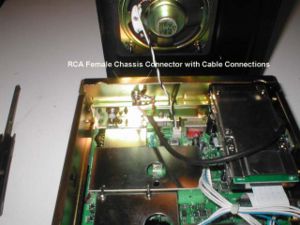
- Remove approximately 1 3/4 inches of outside insulation from the A/V cable. Separate the braided ground shield from the center conductor cable and remove approximately 1/4 inch of insulation. By trial and error measurements configure the A/V cable to allow non-stressed solder connections of the center conductor and braided shield ground to the connector. Remove any solder debris. See Photo 2 for what the modification looks like at this point.
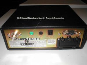
- Reconnect the receiver's speaker wire connector to the pc board and replace the BOTTOM case cover. See Photo 3 of the rear chassis mounted connector.
- Reconnect the power supply and antenna connector to the receiver. Turn on the receiver. If receiver performance is not within specification, check the capacitor/cable routing/connections. Inspect to ensure the capacitor is not shorting out. If it is provide additional insulation around it. Replace the case cover and reconnect the power supply and antenna.
- Calm down and stop shaking. The modification is finished.
- Let the Tests Begin.
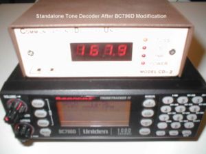
- Scenario 1. BC796D and standalone CTCSS tone decoder. Using a standalone analog/digital tone decoder connect the male RCA cable connector to the BC796D RCA female unfiltered audio connector. On the BC796D select any frequency search or scan range of low or high vhf or uhf . Watch the tone decoder display. The analog or digital CTCSS tone for analog radio transmissions using CTCSS display, if present, displays within a second. See Photo 4.
- Scenario 2. BC796D/Dataslicer RS232/Trunker 3.8.3. interfaces. Trunker 3.8.3 is a freeware MS DOS software program used in conjunction with unfiltered audio input to a Level 2 or 4 data slicer. The dataslicer output inputs to the computer via a RS232 comm port interface. Trunker 3.8.3 is designed to operate in a boot up MS DOS mode. However, on some computer models it will work in the MS DOS shell mode from Windows. Don't throw away those older computers as they have value for this type of application. Trunker 3.8.3 allows the radio monitor to view in real time various talkgroups of 400 and 800 mhz. Motorola Type I and II trunked radio transmissions that also display on the BC796D.
By radio monitor keyboard entries talkgroups can be color coded to provide more meaningful informational talkgroup displays. For example, police talk groups can be color coded blue and blink for a few seconds when initially active; fire talk group may be coded red; rescue talk groups magenta, utilities talk groups yellow, etc. Photo 5 shows the BC796D interfaced with a Level 2 data slicer and Trunker 3.8.3 on a local area 800 mhz. Motorola Type II TRS.
The BC796D unfiltered audio output removes the requirement of having to use another modified receiver/scanner tuned to the desired TRS control channel frequency to provide the same unfiltered audio input to a Level 2 data slicer and Trunker 3.8.3.
One performance tradeoff negative was noticed as a result of the BC796D scanning in the trunked mode.
Occasionally the control channel audio output momentarily was interrupted which resulted in an occasional missed talkgroup monitor display. No talkgroup display was missed on the BC796D. An occasional missed talkgroup condition using Trunker 3.8.3 also can occur with a dedicated standalone receiver/scanner tuned to the control channel due to heavy TRS communication traffic volume. Etrunk 3.8.1 for a local area EDACS TRS was tested and performed similar to Trunker 3.8.3. Other than noted both software packages and the BC796D performed as designed.
- Parts/Component Sources
- .01 mF Ceramic disc capacitor
Radio Shack Catalog Number 272-131
- Shield Phono Jacks Panel Mount
Radio Shack Catalog Number 272-346
- Audio Visual Insulated Cable
Radio Shack Catalog Number 15-1591
- Related Links
- Trunked_Radio_Decoders Trunker 3.8.3 and Etrunk 3.8.1 Software
This article was supplied by the author and is reproduced here with his permission. Any commercial resale or reuse of this article or the information contained here is expressly prohibited
(c) 2006 by John Wilson W4UVV email: w4uvv at amsat dot org


