Grounding Bulkhead with supressors for your scanning station
From The RadioReference Wiki
Contact with high voltages from electricity or lightning is deadly. Consult a licensed professional before you design, build, connect to or operate any kind of electrical grounding system or lightning protection scheme. Neither the members of the RadioReference.com Wiki nor Lindsay Blanton assume no liability for any material or advice presented here, all of which is for purely educational purposes.
Here is some great info on grounding, check it out! I have always used this site for info. There is so much information on the internet about grounding that sometimes may make your head explode. Again, I am no professional and just trying to make my shack a little safer and mostly to give people some simple insight on grounding, but also not spending a ton of money doing so. This project will be mounted on my Tilt-Over that is in the Wiki.
Yes, You NEED to bond your electric power entrance ground to your radio station ground, AND you NEED to bond your tower ground to the rest of your ground system. BOND all grounds together! It is a very good idea to add some 8 foot ground rods every 20 or so feet along your bond wire path if running for a long distance. Always add weather protection to ground rod connections. Products such as RTV Compound, or roof patching tar make for electrical joints. Use an anti-oxidant compound to coat the conductors before connecting them together as a further protection from weatherization. Many are available, I am using Ideal Noalox.
I purchased this outdoor equipment box from my local electrical supplier.
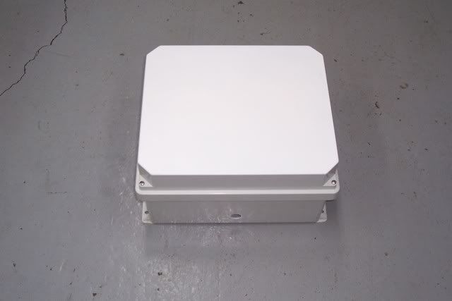
For the inside bulkhead I already had a piece if of 1/4" aluminum to mount all my ICE suppressors.A rack panel of 1/8" thick aluminum is quite nice and easy to obtain through electronic distributors. Copper plate is ideal if available, but even a steel plate is acceptable. A bulkhead plate is defined as a high integrety, zero or low inductance earth terminal connection. For that reason a bulkhead plate should always be placed very close to or on the ground with its lead connections to earth entry point very short - preferably less than a foot long.
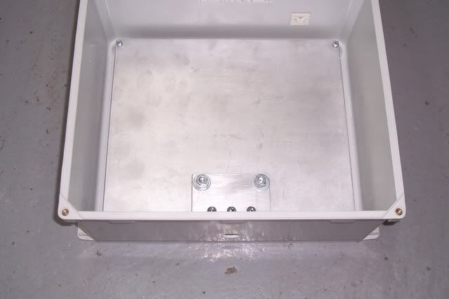
I built this grounding hub fitting but can be bought Here. This hub is mounted on the aluminum bulkhead in the box and is directly going to be mounted on a ground rod. Remember that all equipment that will be mounted on this bulkhead will be coated with Anti-oxidant to ensure good conductivity, More on that later.
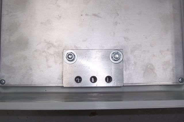
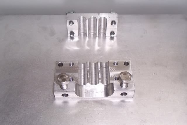
This picture below is a grounding block that I built(but can be bought Here) for my coaxial cable shields and is one of the most beneficial and inexpensive procedures that communication owners can undertake to reduce ground level leakage radiation, lower receiver noise, provide direct shunt control of lightning currents and establish common-point neutral. This is also directly mounted on the bulkhead before the cable is connected to the suppressors. Some info on why these could be an important part of your grounding system Here.
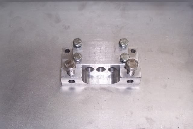
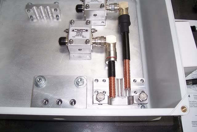
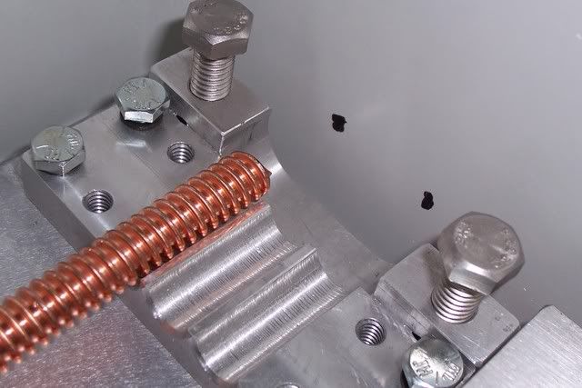
Here is my heliax cable that is stripped for reference and shows how it is mounted in/on the ground block.
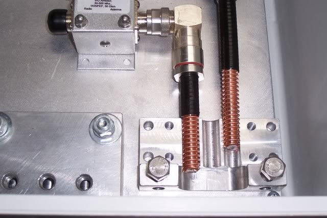
A little closer shot of the hub.
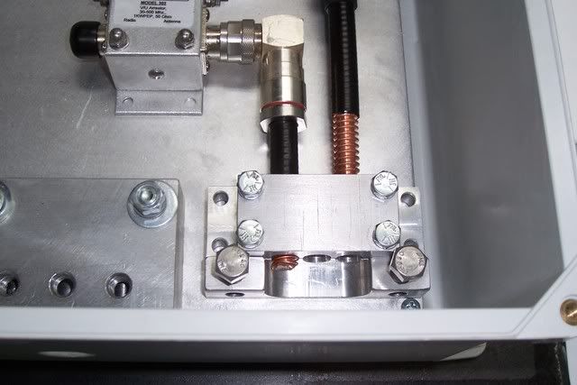
Here is a picture with the top on the hub.
Those example heliax cables that are connected to the ICE suppressors will be coming from the antennas and will have to drill some holes in the bottom of the box when installing. Here is another picture.
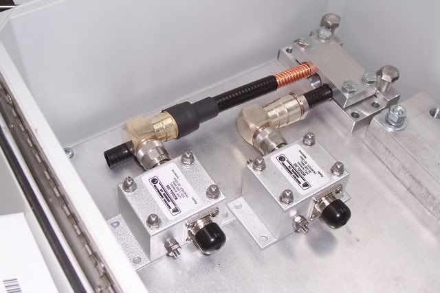
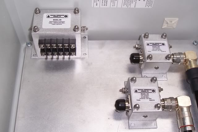
This picture below shows the ICE suppressors for my Omni,LP log and rotor that are all going to be mounted on the bulkhead. ICE suppressors offer a complete, nearly perfect blocking/shunting system for induced voltages. Whether produced by lightning (directly or indirectly coupled), wind, rain, or snowfall I.C.E. arrestors are continuously active, constantly draining transmission line center conductor to ground. The result? Solid protection for station equipment and related noise. Right now, I am just trying to fit and configure everything before actually threading holes and permently mounting the equipment.
This is the hole where the rod comes through the box and mounted directly on the ground rod.
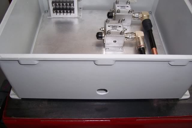
Here is a pic of the inside where the rod will come in.
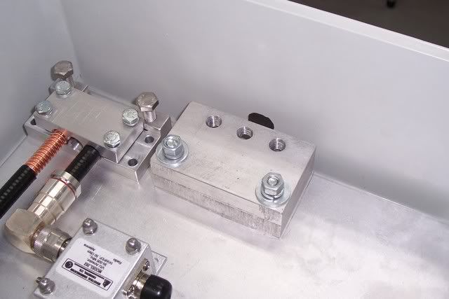
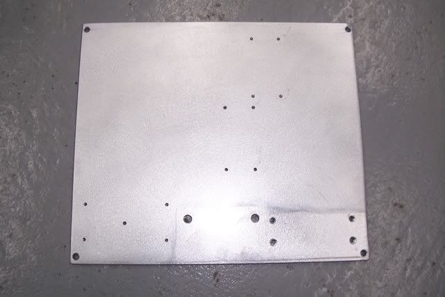
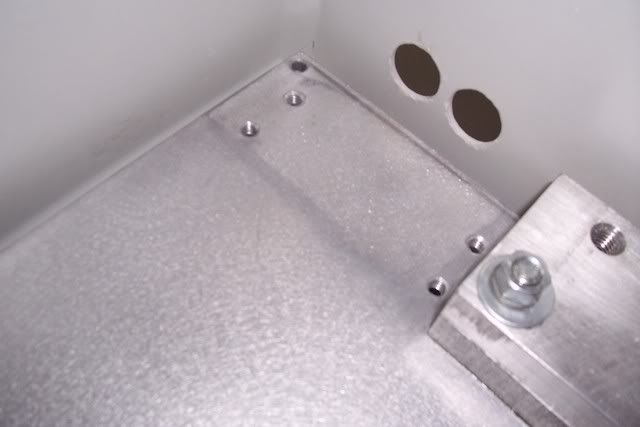
After figuring out where my protectors will go on my aluminum plate I marked all the mounting holes for me to drill and tap. You do not have to drill and tap, you can simplly use the bolt and nut method.
Now it is time to mount the grounding lug using some anti-oxidant compound.
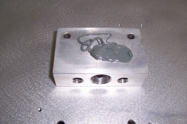
Make sure you spread the anti-oxidant all over the grounding block. Use anti-oxidants in a liberal manner when making connections.
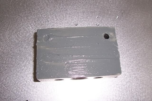
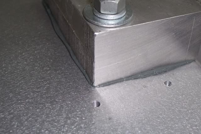
This picture below is after tightening down the block, allowing excess compound to squirt outward from the joint when pressurized. This excess may be easily captured for reuse.
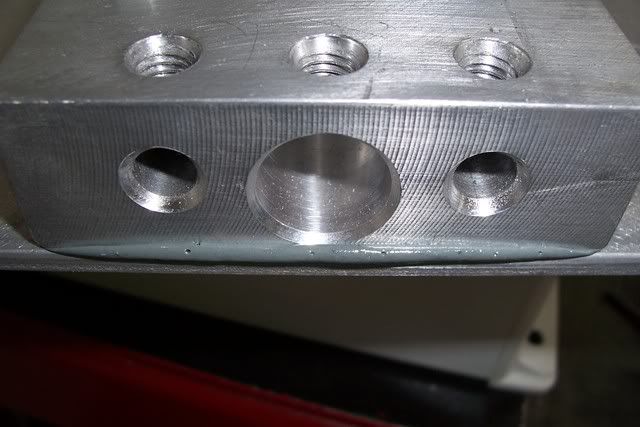
Before mounting my cable sheild block with the anti-oxidant, I wanted to mark and drill the holes for the coax cable and use rubber grommets to keep the weather out.
Below I drilled the holes with a hole saw to add my grommets.
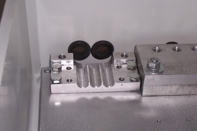
Here are the grommets in place.
I finally finished painting the tilt-over, so before I lifted it I install another coax shield block just below the mast where I will connect a ground cable from the block to the mast.The connections for grounding should always be done at ground level if maximum value is to be obtained, and the lead length from shield to earth entry point (the dirt) should be kept as short as possible - less than a foot if possible. Using a commercial grounding block is a very neat way of accomplishing the task, but making your own shield connections can be done as well like I did. I wish I took a better picture, sorry about the quality. This is the with the outer cable stripped.
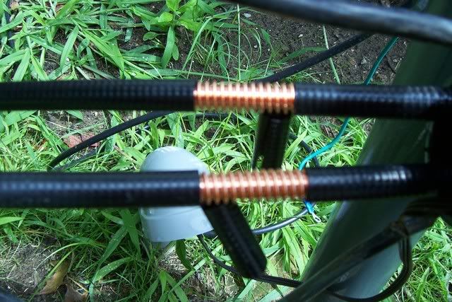
Here is the block installed around the cable and if you look closely you can see the anti-oxident coming out of the block and is totally filled, just wipe of the left over and put it back in your container for later use. After wiping the anti-oxident off I sealed it with black Tremco polyurethane so no water will enter that block. The 2 threaded holes is for the grounding cable that will be attached to the mast and the other is going to be run back to the grounding bulkhead and attached there.
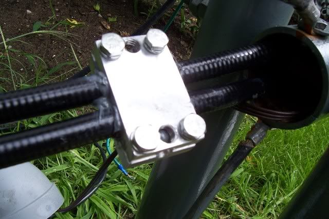
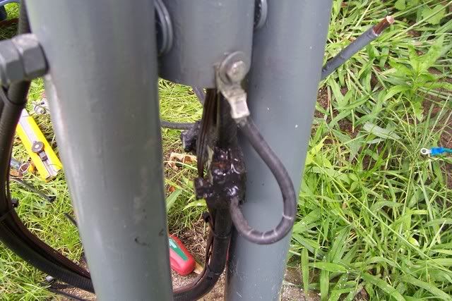
Finally starting to mount the suppressors down on the aluminum with the screws and also coating the backside of the suppressors with the anti-oxident.
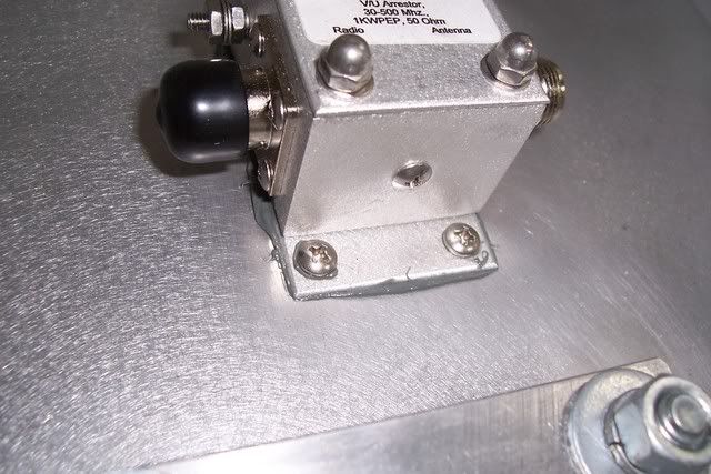
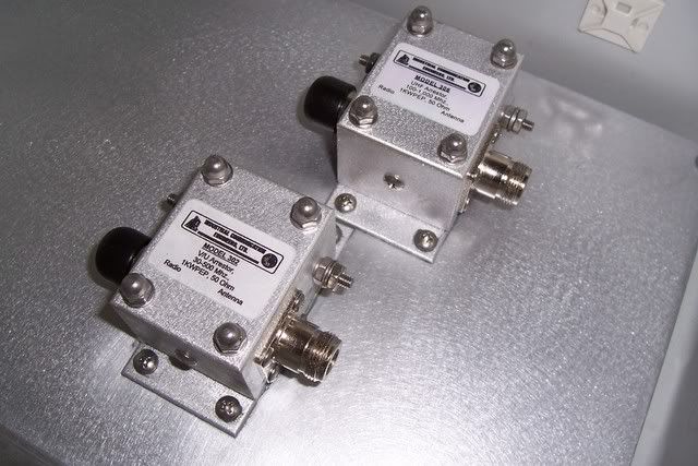
Here is a shot of both suppressors mounted. Notice the excess compound coming out from the back. This will be wiped up and put back in the container.
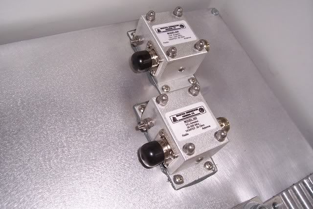
The suppressors after the compound is all wiped off.
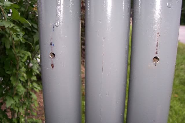
Time to mount the flat bar on the tilt-over so I can bolt the box on. Drilled the holes and tapped the threads.
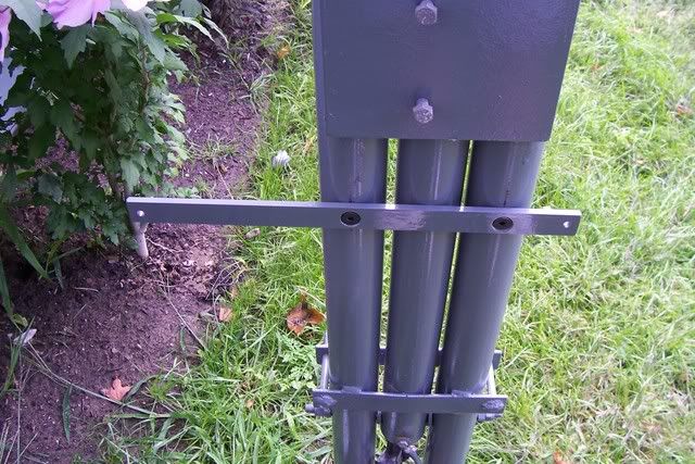
The flat bar installed with some counter sunk bolts.
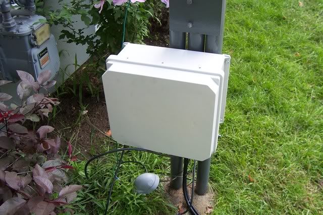
The weather proof box is up and ready to put the cables through.
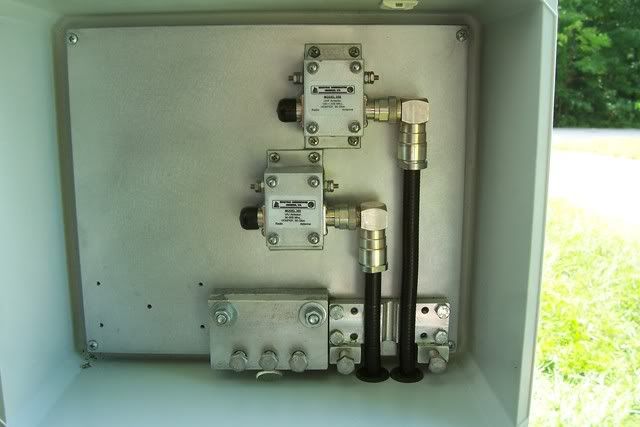
I installed the connectors on the heliax so I can mark the cables on where I have to cut for the sheilding.
The pic below is the outer part of the cable stripped to mount on the ground sheilding block.
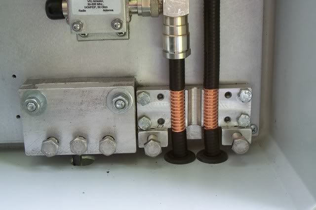
Appling the anti-oxident in liberal manner here and all connections! Electrical contact between metal surfaces, especially between dissimilar metals can be rapidly compromised in the presence of oxygen, water, salts, pollutants, and other oxidizing agents. Aluminum antenna element material, copper grounding electrodes and even the integrity of mated galvanized tower section joints can he secured and improved with the application of conductive surface coatings.
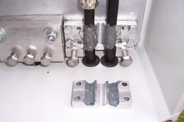
The picture below shows the top part of the block squeezing all the excess material out. You know that all the parts have been covered nicely.There is nothing inherently wrong with using dissimilar metals in direct contact. But if the joint is exposed to air, or if the joint commonly passes a great amount of current then the oxidation that occurs in the metals will accelerate and eventually the connection will fail.
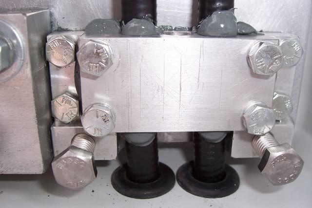
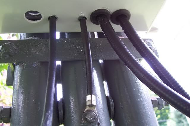
Here is the ground cable coming from the sheild block and is returned back to the mast. Bond everything.
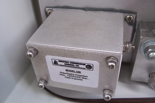
This is the suppressor for the rotor cable mounted with the anti-oxident.
I mounted some more electrical piping from the ground all the way to the box. It just gives it the clean look.
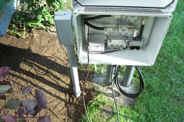
Here you can see the cables on the left side of the box that come from the house and all connected to the supressors.
As much as I wanted to have a ground rod to be connected right to the grounding block it was not really possible because of the concrete for the mast. So it will have to be connected with #1 gauge wire for now until I figure something out to make a solid connection with some more ground rod bent into the shape I want. The lenght of the cable is about 18". Remember to keep all your cables as short as possible. Here is a picture of the #1 gauge wire.
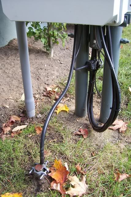
I added a second copper clad ground rod which is buried to the other side of the mast and is connected to the bottom of the mast. You can see the #6 copper wire going into the ground and is connected to the rod. All connectors are sealed up with rtv sealant so they won't be corrodid underground.
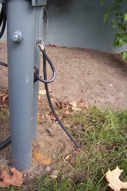
The 2 grounds rods that you see in this project are bounded together underground and sealed with rtv sealant. From the second ground I have #6 wire running all around the house and is connected to my AC panel ground rod. Along that cable,about every 15' or so, I connected more ground rods (3 all together) until I reached my house panel ground rod and bounded there. It is now a common ground system.
I hope some of you have enjoyed reading this to have some idea on how to ground your system to give you some protection from the very powerful strike of lightning.
Places to purchase suppressors and accessories:
Some reviews:
Lightning & Surge Protection/Supression
Tonsoffun Ron
Return to Wiki pages: HF Antennas, RF Engineering, Scanner Antennas
(No matching DB page)