Difference between revisions of "IC-PCR100"
From The RadioReference Wiki
(SWLog is gone) |
|||
| Line 61: | Line 61: | ||
* [http://members.cox.net/fiftyone.50/TrunkPcr/pcr100.html Discriminator Tap Instructions for the PCR-100] | * [http://members.cox.net/fiftyone.50/TrunkPcr/pcr100.html Discriminator Tap Instructions for the PCR-100] | ||
=== 10.7 MHZ IF Output === | === 10.7 MHZ IF Output === | ||
| − | The buffered 10.7 MHz IF Output is available at the | + | The buffered 10.7 MHz IF Output is available at the output (pin 5) of IC5. References throughout the Internet to Q85 are only related to the PCR1000, a different Icom product. IC5 is located on the bottom of the PCB. When looking at the bottom of the PCB, with antenna terminal to the top and right, IC5 is located immediately below and to the left of the center-most mounting screw, within the RF shielding box. Pin 5 is diagonal from the pin with the dot above it (Pin 1), and is the closest pin to the mounting screw. |
| + | |||
| + | This output will carry either 4.1V or 1.7V depending on filter selection elsewhere in the signal path. Depending on your use, a small capacitor such as a .22uf bipolar should be used inline with this signal to protect external hardware from this voltage. | ||
| + | |||
| + | All above information can be readily explored in the ICOM IC-PCR100 Service Manual #A-5548MI-S(1998) and associated schematics and board layout. | ||
=== Other === | === Other === | ||
Revision as of 08:57, 26 February 2007
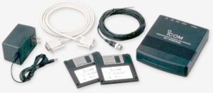
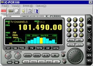
This page lists links, related pages and software support for the Icom PCR-100 receiver.
Contents
General Specifications
- 10kHz-824MHz, 849-869, 894-1300MHz range (USA)
- Scan rate 16cps
- WFM, FM, AM, Auto
- 1000 channels per file (50 channels x 20 banks)
- 1, 5, 6.25, 9, 10, 12.5, 15, 20, 25, 30, 50, 100, 500kHz; 1MHz steps
- CTCSS
- Attenuator
- Automatic noise limiter (ANL)
- Narrow/wide filter
- Autostore
- 20 search limits
- Signal meter
- Bandscope
- Icom PCR-100 Specs
Reviews and User Opinions
Related Pages
Supporting Software
- Bonito Radiocom 5
- IP1KC
- IP1k2
- PCR Remote
- PCScan
- RadioControl
- Radiomax
- Scancat
- Spectrum Commander
- Spectrum Dominator
- Spectrum Manager
- TalkPCR
- TrunkPCR
Yahoo Groups and Mailing Lists (software and receiver support)
- Scancat Yahoo group
- Shortwave Log User's Group on Yahoo
- Spectrum Commander Yahoo group
- TalkPCR Yahoo group
- TrunkPCR Yahoo group
- Icom Forum at Strong Signals
- Icom Forum at RadioReference
Modifications
Discriminator
10.7 MHZ IF Output
The buffered 10.7 MHz IF Output is available at the output (pin 5) of IC5. References throughout the Internet to Q85 are only related to the PCR1000, a different Icom product. IC5 is located on the bottom of the PCB. When looking at the bottom of the PCB, with antenna terminal to the top and right, IC5 is located immediately below and to the left of the center-most mounting screw, within the RF shielding box. Pin 5 is diagonal from the pin with the dot above it (Pin 1), and is the closest pin to the mounting screw.
This output will carry either 4.1V or 1.7V depending on filter selection elsewhere in the signal path. Depending on your use, a small capacitor such as a .22uf bipolar should be used inline with this signal to protect external hardware from this voltage.
All above information can be readily explored in the ICOM IC-PCR100 Service Manual #A-5548MI-S(1998) and associated schematics and board layout.
Other
eBay Listings
Back to Icom Radios

