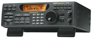
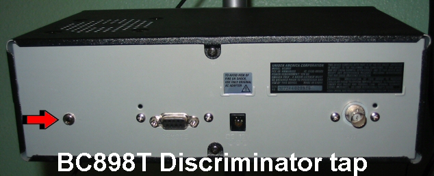
BC898T Discriminator Tap
From The RadioReference Wiki
Contents
Introduction
This document is about installing a discriminator tap in a BC898T. This document will not explain the theories behind Discriminator output or the Trunked Radio Decoders used with discriminator taps.
Credits
Credits to Anthony W. Waukap of http://myweb.accessus.net/~090/bc-780xlt.html His work on the BC780XLT was the starting point of my quest to install the tap of the BC898T. I also would like to credit those before Mr. Waukap that took the risks and the time to document their work on discriminator taps.
Copyright
This work is protected under GNU. Which means, give credit. You can add on to it. DO NOT restrict access or demand fees or donations to view it.
Caution – Warning
Here's the steps I took to tap the BC898T. I'm not responsible for anything that might go wrong if you try it. Installation steps including using a soldering iron or gun. It's hot and will burn you severely! Do not over heat the LND12 solder point. No implicit or suggested warranties applied.
Installation
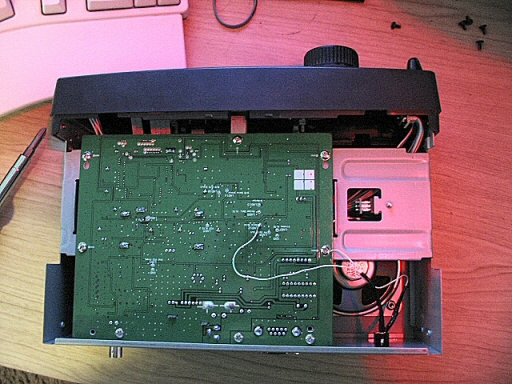
Let's start with the BC898T case:
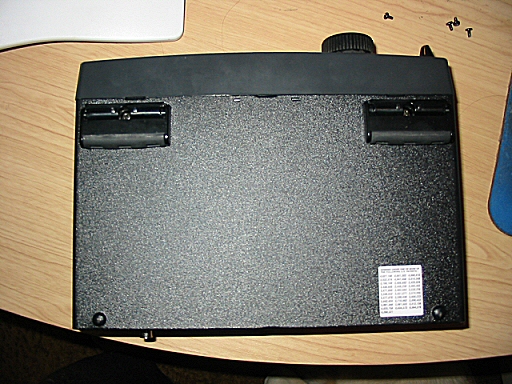
- Remove the 5 screws from the bottom case - 2 screws left and right of the case and one in the back
- Locate a place to drill the 1/4 hole for the phone connector (radio shack number 274-249).
- Put a cloth or something down inside the case to ketch the metal filings when the hole is drilled.
- Start with a pilot hole using a small drill bit.
- Use a 1/4" drill bit to make the hole the correct size.
- File any sharp edges
- Search for any metal filings in the case and remove them.
Installing wire to a resistor and phone connector connections:
- Remove the phone connector nut from the phone connector. You will be using the nut later.
- Find wire -- it can be solid core or stranded. In this example I choose wire used from a network cable.
- Cut two lengths of 8-10 inch wires.
- Strip ½ inch off the insulation on both sides of each wire.
- Examine the back of the radio shack package you will see numbers corresponding with the phone connectors.
- Connect a 10k ohm 1/4 watt resistor lead to the 1 terminal of the phone connector.
- Connect a wire to other resistor lead. Again, twist the wire and the resistor lead.
- Connect a wire to the 3 terminal of the phone connector. Twist the wire it will be easier to soldier.
- Solder the 1 terminal and the resistor lead
- Solder the wire to the resistor lead
- Solder the second wire to 3 terminal.
- Install the phone connector in the hole with the jack facing out.
- Install the phone connector nut firmly on the phone connector.
Installing wires on the main board and main board case mounting screw and final assembly:
- Warm up a soldering iron.
- Clean the soldering iron tip on a damp sponge.
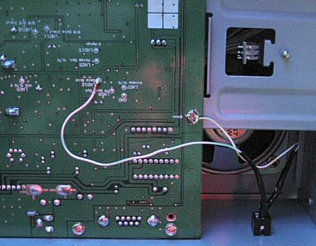
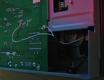
- Locate the wire soldier to the resistor (1 terminal of the phone connector).
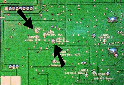
- Add a little solder to the wire tip. Just a little and no more. Place the end of the wire on LND12 soldier point.
- Put the “hot��? soldier iron tip over the wire.
- The solder on the wire should combine with the LND12 solder point. Quickly remove the soldering tip.
- Wait a few seconds and gently tug on the wire connected to LND12. There should be no moment.
- Check the surrounding soldier points to make sure the wire is not in contact and there's no additional solder.
- Locate the main board case mount screw
- Turn the screw counter clockwise one full turn.
- Place the wire end of terminal 3 under the screw
- Firmly tighten the screw clockwise.
- Make any corrections necessary to the wires to avoid case or main board obstructions.
- Place the bottom half of the case back on the BC898T.
- Install the 5 screws to the case.
This is the end of the installation portion of BC898T discriminator tap.
Post Production Notes
- I used heat sink tubing to cover up the resistor and terminal solder connections.
- The 10k ohm resistor is to prevent harm to the main board if a short occurs.
- A capacitor is unnecessary. Most data slicers already have them.
- Ethernet network cable (CAT5-E) is 26 gauge wire.
- The phone connector 1 terminal is really close the to BC898T case. I bent the terminal away from the case.
