Freescan Create Systems
From The RadioReference Wiki
This screen defines a system, which is the highest level in the Dynamic Memory Architecture data structure. It can be created automatically, using the UASD Import, BuTel ARC imports, RadioReference Conventional Import, or the RadioReference Trunked Import functions, or by right clicking in the tree view for all the systems. It can also be accessed by placing the cursor on a system name in the System View (the white shaded area to the left) or by clicking the 'New System' button in the toolbar
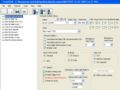
Editing a Conventional System
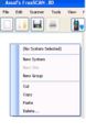
Select 'Create System'
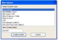
Choose Type and Name
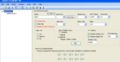
Result


Click on the image to expand it
- Name - The name of this system. The phrase can be justified using the symbol bars in the upper right of the field, or by using the Justify Channel Names function
- Quick Key - The System Quick Key (SQK) attached to this definition. The Find Free button will attempt to identify the next available SQK; however you can use the pulldown to define your own selection. See the Freescan Tools functions under the System Quick Key Manager to enable/disable System Quick Keys
- Startup Key - BCD996, BCT15, BCD396XT and BC346XT only. Enables the scanner to power up using only systems defined with this key. To enable this function, press the appropriate keys for the desired system when powering up. Can apply to systems, sites or searches.
- APCO Mode See the P25 audio decode level adjustment article for a full discussion of this parameter
- Threshold See the P25 audio decode level adjustment article for a full discussion of this parameter
- Locked Out - If checked this system, and all its components are locked out of scanning
- Data Skip - If checked the scanner ignores conventional data transmissions and some birdies.
- Hold Time - The number of seconds the scanner will wait while scanning a system. The default is 2 seconds
- Delay Time - The number of seconds the scanner will wait on each frequency in the system. This cannot be set on a per-channel basis. Note that for the XT scanners, negative values are now supported
- State (BCT15/15X only) - Selects the state-by-state programming in these 2 radios. If it isn't desired, be sure to select OFF. FreeScan uses this to disable the BearTracker function in these radios.
- Tape Out - BCD996, BCT15, BCD996XT and BCT15X only. OFF indicates no audio from any component in this system will be sent to the tape out jacks, MARKED sends only those so indicated on the Create/Edit Group screen and ALL is self explanatory. Note that recording needs a separate connection from the tape out jack (or for the handhelds, the earphone) on the scanner to the soundcard in your PC. This is discussed in detail in the Connecting Radios to Soundcards article
- GPS - BCD996, BCT15 only Indicates use of the GPS function. Be sure to click on the Enabled box. Pressing Edit GPS Settings displays the GPS Settings screen, where locations and ranges may be defined. See the FreeSCAN-GPS article for more information
- Quick Key Enable/Disable - Enables/Disables Group Quick Keys (GQK). Those that are checked are enabled and should match those listed in the System View
- These controls are specific to the XT scanners:
- Enable Analog AGC : This setting helps balance the audio level you hear as you listen to different radio sources so you can hear them at a similar volume.
- Enable Digital AGC (BCD396XT, 996XT only) Same as above, but for digital systems
- Number Tag: See the Number Tags section of the Easier to Read manuals for your scanner
- P25 Wait Time (BCD396XT, 996XT only): this setting basically gives the scanner time to determine if channels on conventional systems have digital or analog transmissions. During this time, the scanner will evaluate the received signal and, if it detects P25 data, will open squelch immediately. If P25 is not detected before the delay expires, the scanner will open squelch at the end of this delay. This is to prevent "false decode" problems (digital noise at the beginning of transmissions). The default setting is 400 ms. This setting only affects conventional channels with an Audio Type set to All. Note that Any analog transmissions will lose the first part of the transmission, up to the wait time you set here
- CAUTION System Protect Before you wipe out your programming experimenting with System Protect, read the following:
- Once System Protect is enabled and the system is uploaded to the scanner, System Protect cannot be turned off. Protect will lock down the affected system to both the user and FreeSCAN. This means that the user going through the front panel cannot delete or modify a protected system other then locking out channels. If you try to access it through the programming menu, the scanner will deny access. Protected systems can't be downloaded back to software. It's a one way trip only. If you try to download a protected system, all the scanner will send are blank channels. You can still delete a protected system using FreeSCAN as you would a normal system. But it cannot be deleted through the front panel.
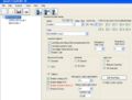
Editing a Trunked System
Select 'Create System'
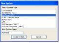
Type 2/P25 selected
Type 2/P25 created
Type 1 system
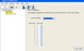
Fleetmap screen


All fields defined in the Conventional section are found here with these additions;
- Type - If you allocated this system manually, the system type should appear here. Importing from the UASD or RR will define this for you. This sets the type of trunked system being defined.
- Note that there is a bug in defining an EDACS system. It will default the system type to EDACS Narrow. This might not be correct for your area. It's advisable to define this as EDACS standard/wide unless the RR Database tells you otherwise.
- Use Motorola Status Bit - This function defines how the scanner will display talkgroups that indicate various functions are being used on the system, such as system patches. See the Motorola Talkgroups article for a discussion of status bits
- Use Motorola End Code - Sets how the scanner will process the code sent by many Motorola systems at the end of a conversation. Checking this box will send the scanner back to scanning or searching (dependent on what mode the system is set). If the system is noisy or weak, the end code might be mistaken for a noise burst or other interference. If this is the case, leave it unchecked.
- Use Digital Motorola End Code - Similar to the analog end code, but for P25 systems
- Enable I-Call - To enable monitoring of I-Call.
- EDACS ID Format - used to define the display/use of talkgroups in EDACS systems only. AFS is an abbreviation for 'Agency Fleet Subfleet' and is always written xx-yyy. The 'dash' is usually entered with the period key.
- ID Mode - ID Search will display all talkgroups encountered, without referring to the list of talkgroups defined to the group. ID Scan will display only those talkgroups in the list.
- Edit Fleet Map - Only applicable to Motorola Type I and Motorola Type IIi Hybrid systems. If you had chosen to create a type 1 system, the result would be as shown. Notice that this button is now available. You will need to define a series of Fleet maps on the appropriate screen so the system will be properly tracked. See the type 1 article for a discussion of fleet maps and their components. Most often the RadioReference database already has this information; you will need to add this manually as the web service cannot import this data.
- Emergency Alert Type See the Easier to Read manual for your scanner
- Emergency Alert Level The volume level for the alert type
- Emergency Alert Light Pattern (XT Scanners only) The light pattern used when the emergency flag is set. Values are slow or fast blink
- Emergency Alert Light Colour (XT Scanners only) The color used when the emergency flag is set. Values are Blue, Red, Magenta, Green, Cyan, Yellow, or White
- Priority ID Scan Applies priority to those talkgroups marked for it in this system
Some of this comes from the Easier to Read manuals
Proceed to the Create/Edit Site article
Return to the FreeScan User Guide